I have quoted automotive brackets for more than twenty years, and the same argument shows up at nearly every kickoff. The design team wants +/- 0.02 mm everywhere because a CAD model makes it look free. The buyer wants the lowest cost per part on the table. Both positions are wrong, and the drawing is where that fight gets settled. Bracket tolerances sit in the middle: loose enough to make at volume, tight enough that the module assembles without shims, rework or a warranty claim two winters later.
Contents
- Why bracket tolerances get scrutinized
- The tolerances that actually matter
- What suppliers must prove rather than claim
- What each process can hold
- PPAP and the documents behind the numbers
- Common tolerance mistakes on bracket drawings
- What tight tolerances do to cost per part
- Frequently asked questions
Why bracket tolerances get scrutinized
Brackets rarely fail on strength. They fail on location. A bracket 0.3 mm off position can drag a harness into a hot surface, push a pump seal off axis, or turn a squeak into a field recall. That is why automotive customers treat bracket drawings with more suspicion than the geometry deserves.
The scrutiny also comes from the supply chain. OEMs run IATF 16949 based quality systems, and they expect every tier below to demonstrate capability instead of only inspecting finished parts. When a sourcing engineer asks about your automotive bracket tolerances, the real question is: can you hold these numbers across 50,000 parts with data to prove it? I have watched suppliers pass a first article and then drift out of tolerance by piece 800.
There is a cost angle too, and the sections below give the numbers I use when I review a bracket drawing.
The tolerances that actually matter
Most of a bracket is filler. The functional area is small, and it usually comes down to three things.
Hole position. For clearance bolt holes carrying only a clamp load, +/- 0.10 mm position is plenty; I have shipped millions of brackets at that number without an assembly complaint. When the bracket locates something, a sensor body, a valve, a module with its own fit, position tightens to +/- 0.05 mm, and the hole itself usually needs to be machined rather than cast or formed.
Flatness on the mounting face. A mounting face that bows 0.3 mm will preload a housing when the bolts go in. On a 100 mm mounting face I specify flatness of 0.1 mm as default for loaded brackets. Below 0.05 mm you are into machining or grinding, and on castings expect the foundry to push back.
Perpendicularity of the load path. A boss or flange carrying the main load should sit square to the mounting face, usually within 0.1 mm over its height. Skewed load paths fatigue fast. This gets skipped on drawings more than any other and costs nothing to state.
Everything else can ride on general tolerances. ISO 2768-m gives +/- 0.3 mm on a 50 mm dimension, which sounds sloppy until you notice it applies to pads with no position requirement. Blanket tightening the title block to +/- 0.05 mm does not make the bracket better. It makes the quote 40 percent higher and the rejection pile bigger. For a second opinion before a drawing goes out, see our guide on how to prepare CAD drawings for a CNC machining quote covers the quoting side of the same problem.
What suppliers must prove rather than claim
Here is the sentence I want every buyer to memorize: a tolerance on a drawing is a promise about distribution, not about one part. The question is not whether piece 1 measured 49.98 mm. The question is where piece 8,000 through 8,100 will land.
Automotive practice answers that with process capability indices. Cpk 1.33 is the standard requirement on general characteristics, and Cpk 1.67 applies to safety related ones, airbag brackets, brake component mounts. The math matters less than the meaning: Cpk 1.33 corresponds to roughly 63 defective parts per million, and 1.67 drops below one per million. A supplier quoting your bracket should show a study on consecutive parts, typically 25 subgroups or 100 pieces, demonstrating those numbers on the characteristics you marked critical.
Measurement quality matters as much as process quality. A gage with 30 percent R&R can make a capable process look marginal and a marginal one look fine. I ask for gage R&R under 10 percent on any characteristic carrying a Cpk requirement. To read an inspection report yourself, see our guide on how to verify dimensional inspection reports and our note on when CMM inspection is actually needed.
What each process can hold
Process selection decides the tolerance conversation before the drawing is printed. On a 50 mm feature, here is what each of the four processes we run holds in normal production, without heroics:
| Process | Typical tolerance, 50 mm feature | Notes |
|---|---|---|
| CNC machining | +/- 0.025 mm | Holds any feature a cutter can reach |
| Powder metallurgy, as-sintered | +/- 0.15 mm | Coining or sizing brings selected faces near +/- 0.05 mm |
| Metal injection molding, as-sintered | +/- 0.20 mm | Complex geometry; machining adds precision where needed |
| Investment casting | +/- 0.25 mm | Excellent for shape, mediocre for size; machine critical features |
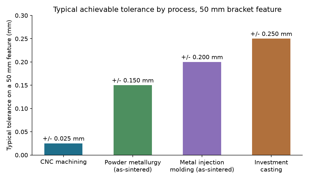
The lesson: match the process to the shape, then buy precision with machining on the few features that need it. A powder metallurgy bracket with two machined bores often beats a fully machined bracket on cost per part at volume, which is why we route many high volume programs through our powder metallurgy line and finish critical features on our CNC machining cells. Complex thin geometry goes to metal injection molding, and large or hollow sections go to investment casting with facing cuts on mounting surfaces.
Material choice moves the numbers too. 6061 aluminum machines predictably and holds tight bands without argument, which is why it dominates machined brackets. Under the car, where salt and gravel live, we shift to 316L stainless or coated carbon steel, and the coating thickness has to be counted inside the tolerance stack.
PPAP and the documents behind the numbers
When an automotive buyer asks what tolerances suppliers must meet, the honest answer is: the ones you can document. The paperwork that carries that burden is the PPAP package; Level 3 is the normal submission for a new bracket. It bundles dimensional results on every drawing characteristic, material test reports, the capability study, gage R&R data, the control plan and the Part Submission Warrant into one auditable package.
I would rather see a modest PPAP package with honest numbers than a glossy one with copied data. If the capability study shows Cpk 1.35 on a characteristic the customer flagged as significant, that is a process you can trust. If every number is 1.68 or 1.71, I start asking which study was run in a hurry the night before the deadline. For the full document list, see our PPAP submission checklist for buyers, and for how the automotive quality system differs from the general one, read ISO 9001 versus IATF 16949. Our how we work page explains what we submit at each stage, and our FAQ covers first order questions.
Common tolerance mistakes on bracket drawings
These five show up on my desk every month, and each one costs the buyer money it did not need to spend.
Blanket tight tolerances. A title block of +/- 0.05 mm on a powder metal or cast bracket is a quote for machined pricing on all faces. The supplier will either price it that way or call you, and the call always comes after the RFQ deadline.
Missing datums. Without a datum scheme, hole position is measured from whoever holds the caliper. I have reviewed drawings where the same hole measured 0.15 mm differently depending on which face the inspector picked first. Three datums, labeled A, B and C in the order the part locates in the fixture, that is all it takes.
Copy-paste from a machined reference part. A design inherited from a machined bracket gets re-sourced as a casting with the tolerances still on it, and the casting house quotes a facing operation on every surface, or declines the job.
Tolerancing the coating away. A 25 micron zinc or e-coat layer adds 25 microns per face. On a +/- 0.05 mm feature, the coating eats half the band. State whether the tolerance applies before or after coating, in writing.
Surface texture treated as an afterthought. A rough as-cast mounting face will not seat a gasket or a sensor. If Ra matters, put the number on the drawing; our guide on specifying surface roughness on a drawing covers the symbols and values.
What tight tolerances do to cost per part
Tolerance decisions are money decisions, so here is the tradeoff quantified. On a machined 6061-T6 bracket, with +/- 0.25 mm on the critical features as the cost baseline, tightening does this:
- +/- 0.10 mm: roughly 1.3x baseline cost per part
- +/- 0.05 mm: roughly 1.8x
- +/- 0.025 mm: roughly 2.6x, and that assumes the features are even reachable with standard tooling
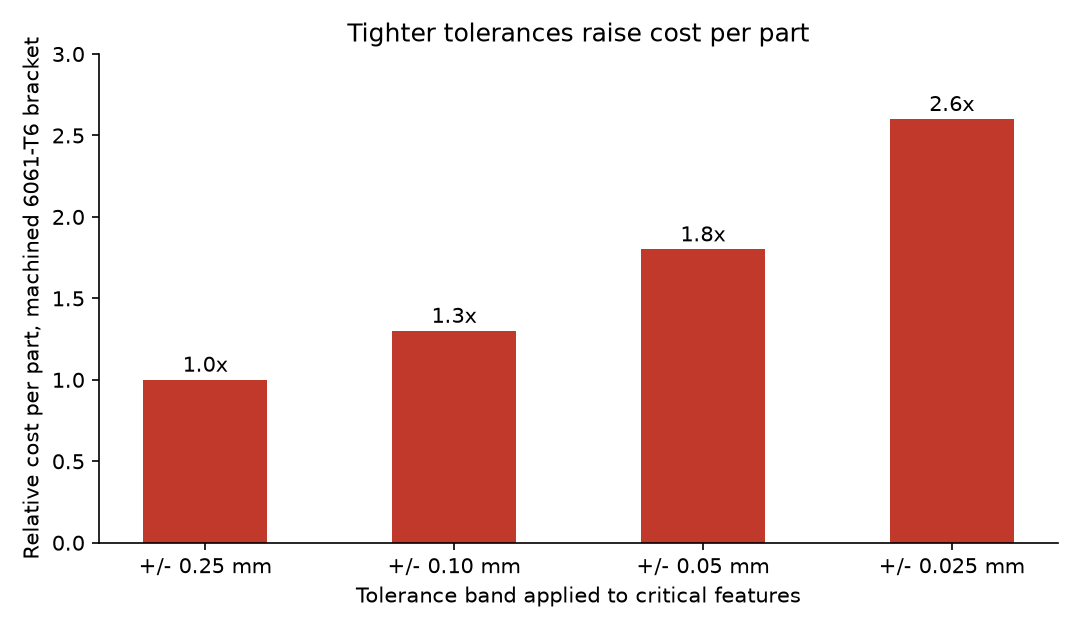
The drivers are unglamorous: extra finish passes, slower feeds, 100 percent inspection instead of sampling, and a scrap rate that climbs as the band shrinks toward the natural variation of the machine. None of this argues against tight tolerances where they earn their keep. It argues for spending them like money, because that is what they are. The same discipline applies around the bracket: our guide on procuring custom brackets for industrial machinery covers the non-automotive version, and our automotive industry page lists the bracket classes we ship, including general industrial equipment programs where the philosophy applies unchanged.
Frequently asked questions
What tolerance should I put on automotive bracket mounting holes?
For clearance bolt holes carrying only a clamp load, +0.2/-0.0 mm on hole diameter with a position tolerance of +/- 0.10 mm is plenty. When the bracket locates a sensor or module, tighten position to +/- 0.05 mm and define datums so the location is measurable. Anything tighter belongs on a machined feature, not the whole part.
What Cpk value do automotive customers require for brackets?
Most automotive quality systems ask for Cpk 1.33 on general characteristics and Cpk 1.67 on safety related ones. Cpk 1.33 works out to about 63 defective parts per million. Ask for the capability study inside the PPAP package rather than a bare claim on a quote sheet.
How much extra cost does a tight tolerance add per part?
On a machined 6061-T6 bracket, going from +/- 0.25 mm to +/- 0.10 mm raises cost per part by roughly 30 percent. At +/- 0.05 mm the index reaches about 1.8x, and at +/- 0.025 mm it can hit 2.6x because of extra finish passes, 100 percent inspection and higher scrap risk. Apply tight bands only where the function demands them.
Can powder metallurgy meet automotive bracket tolerances?
Yes, within limits. As-sintered powder metallurgy holds about +/- 0.15 mm on a 50 mm feature, which covers most clamp load brackets. Coining or sizing brings selected dimensions closer to +/- 0.05 mm, and machining critical bores after sintering is standard practice. Mark the functional features and leave the rest to general tolerances.
What documents prove a supplier can hold the tolerances on my brackets?
Ask for a PPAP Level 3 package: dimensional results on every drawing characteristic, material certificates, the process capability study, gage R&R data, the control plan and the Part Submission Warrant. For a first order, a well filled FAI report plus material certs tells you most of what you need.
Need Precision Metal Parts for Your Project?
Yujiaxin Tech specializes in MIM, CNC Machining, Powder Metallurgy, Investment Casting, and Gear Hobbing. Get a free quote within 24 hours.